RadioRA 3
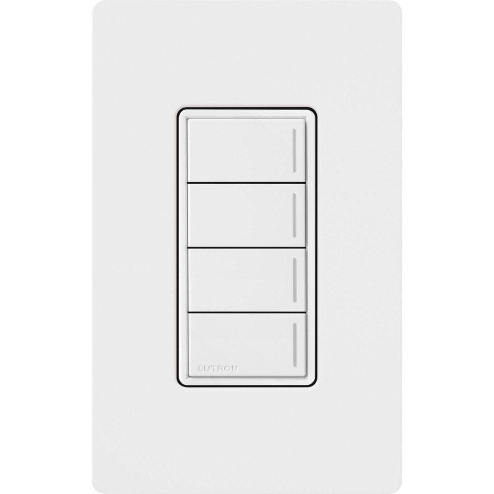
Sunnata RF keypad
A clean wall control for programmed scenes, with engraved button options and status indication.
Official product pageElectrical repairs, lighting, outlets and switches for homes and businesses.
VORTEX CONTRACTOR brings electrical design knowledge, field experience, disciplined coordination, and dependable execution together to help move projects from drawing to installation with clarity and confidence.
Clear scope. Careful work. Documented details.


Who we are
Founded by Yarlos Rodriguez, VORTEX connects electrical design knowledge with field experience to understand, verify, coordinate, and execute.
VORTEX CONTRACTOR is an electrical contracting company built around a technical, collaborative approach to construction. We believe successful electrical work begins long before installation. It begins with understanding the project, recognizing the design intent, anticipating field conditions, and communicating clearly with the people responsible for delivering the work.
Our approach combines electrical design knowledge with practical field experience. We do not see ourselves simply as the team that receives drawings and installs systems. We see ourselves as part of the project team — a contractor prepared to understand, verify, coordinate, and execute.
Our vision
We help close the gap between electrical design and field execution through clear communication and early coordination.
Not every construction condition can be anticipated on the drawings. Equipment changes, existing conditions, available space, sequencing, and coordination with other trades can all affect how a system is installed.
VORTEX brings useful field information back to the project team early enough to support better decisions. Through clear communication, disciplined coordination, and accountable execution, we help protect constructability, schedule, and design intent.
Technical scope
A coordinated electrical construction approach for residential, commercial, multifamily, mid-rise, and high-rise projects.
Our approach is built for electrical construction environments where coordination, constructability, and accountability matter. VORTEX supports residential, commercial, multifamily, mid-rise, and high-rise projects with a disciplined process focused on understanding the work before installation begins.
Panels, lighting, EV chargers, generators and rewiring — with the load calculation shown to you before the price.
How we do it ›Three-phase distribution, LED retrofits, equipment hookups and emergency lighting — sequenced around your open hours.
How we do it ›RadioRA 2 and RadioRA 3 system planning, installation and programming. Try the live scene demo and see how the controls work.
Open the demo ›Our commitments
Four standards that apply to every job, stated in the proposal instead of promised in conversation.
Stay clear of the equipment. If there is fire, smoke or an immediate hazard, call 911 from a safe location. Do not touch a sparking or damaged panel.
Equipment
Equipment is selected for the actual system: listing compatibility, voltage, ampacity, interrupting rating, environment and future serviceability—not by brand name alone.









Our method
The NEC is the technical foundation, not a marketing label. Each scope identifies the applicable code requirements, equipment instructions and project records. Documentation commitments are stated separately from code requirements.
For service changes and added loads, the applicable Article 220 calculation is evaluated alongside equipment ratings, existing conditions and utility requirements. The proposal identifies the calculation basis and the equipment to remain or be replaced.
Conductor selection accounts for ampacity, terminal temperature ratings, ambient temperature and conductor grouping. Voltage drop is evaluated for the actual run and load; a general design recommendation is not presented as a universal NEC limit.
Terminations are installed to the equipment instructions and applicable NEC 110.14 requirements. Where numerical torque values apply, the specified tightening method is followed. The proposal identifies the torque documentation included at closeout.
Equipment grounding and bonding provide the effective fault-current path that lets overcurrent protection operate. The grounding electrode system serves a different purpose and must also be correctly sized and connected; pool areas add the equipotential bonding requirements of Article 680.
When concealed-work documentation is included in the scope, we photograph useful cable routes, boxes, grounding and bonding before closure and organize the images for handover. The proposal identifies the areas and records included so the documentation is complete and usable later.
Permit and inspection responsibilities are defined for the actual scope. NEC 408.4 addresses circuit identification; a typed directory and a digital copy are documentation standards identified in the proposal, not separate NEC format requirements.
Why us
Responsibility is assigned before the work starts, not looked for after something goes wrong.
The proposal identifies the responsible project contact from estimate through closeout, including who can answer technical questions.
Recommendations are explained with the relevant calculation, equipment information and applicable code reference. The proposal records the reason for the recommended scope.
RadioRA 2 and RadioRA 3 controls are coordinated with the exact loads, devices and manufacturer requirements, with permits and inspections whenever the work requires them.
The difference
These are the verification points and deliverables to define in the proposal. They describe the planned process, not a claim about projects already completed.
Yarlos Rodriguez founded VORTEX to connect electrical design understanding with real-world construction experience.
Yarlos Rodriguez founded VORTEX CONTRACTOR after experiencing electrical projects from both the field and design perspectives. Field experience provided a practical understanding of how systems are built, how conditions affect installation, and where constructability challenges develop. Electrical design experience provided a deeper understanding of design intent, technical responsibility, and the decisions behind the drawings.
VORTEX was created to connect those perspectives — not to replace the engineer or question the value of design, but to contribute field knowledge that helps the entire project team make better-informed decisions.
Founder · Yarlos Rodriguez
Our approach
A disciplined four-step process that turns technical understanding into accountable field execution.
We begin by understanding the scope, design intent, project requirements, and construction constraints, then confirm field conditions before they affect the work, communicate technical information clearly and early with the project team and other trades, and execute safely and cleanly from installation through completion.
We begin by understanding the scope, design intent, project requirements, and construction constraints.
We confirm field conditions, equipment information, ratings, dimensions, and installation requirements before they affect the work.
We communicate technical information clearly and early with the project team and other trades.
We execute the work safely, cleanly, and with accountability from installation through completion.
Handover
A practical closeout package helps the owner operate, maintain and modify the installation without guessing later.
Closing
From drawing to installation, VORTEX brings clarity, coordination, and accountability to electrical construction.
VORTEX CONTRACTOR brings design knowledge, field experience, and technical communication together to help move electrical projects from drawing to installation with clarity and confidence. We work to become a dependable project partner for owners, general contractors, engineers, designers, and construction teams.
Lutron systems
Controls, keypads, scenes, load compatibility and motorized shades coordinated from installation through programming.
Real equipment
Actual Lutron product photography for the devices and shading equipment we coordinate, install and program according to the selected system.
A clean wall control for programmed scenes, with engraved button options and status indication.
Official product page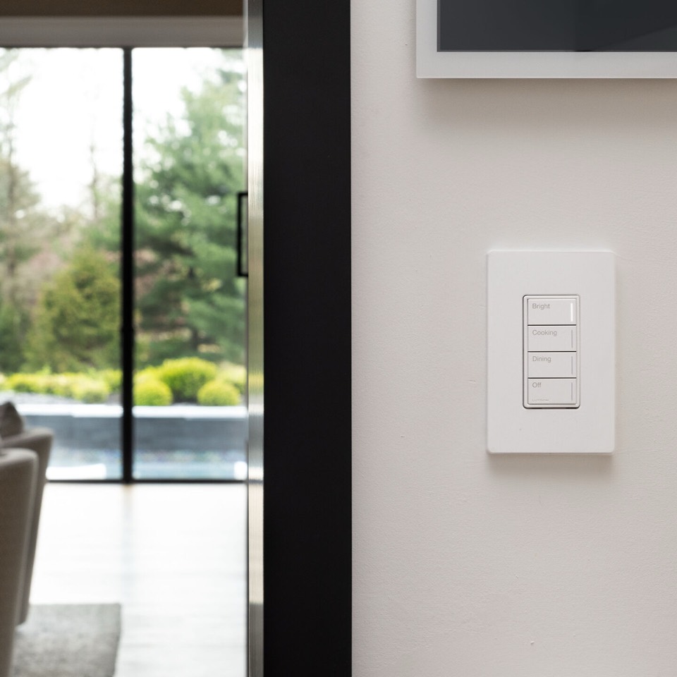
Keypad intent, loads and scene levels are documented before programming so every button has a clear purpose.
Official product page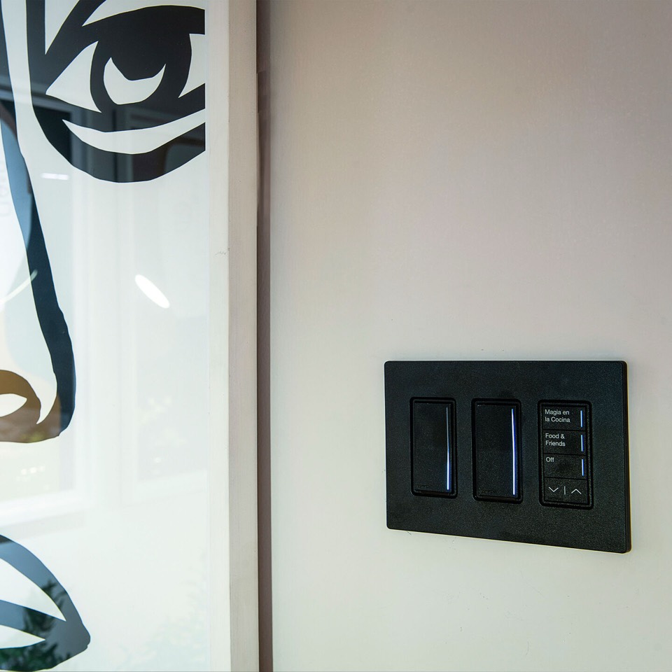
Device colors, wallplates, engraving and button intent are coordinated before ordering instead of decided after installation.
Official product page
Shade power, pocket conditions, fabric selection and controls are coordinated before installation and commissioning.
Official product pageScroll — the room follows. Or press a button on the keypad.
You come in at night with your hands full. One press and the kitchen, the hallway and the cove come up together over three seconds. Nobody stands in the dark feeling along a wall for the right switch out of five.
The downlights drop to 30% so nobody is lit from directly overhead. The cove carries the room, the pendants hold the island where the food is, and the shade comes down a quarter to kill the reflection in the window.
Pendants rise while ambient layers dim and the shades close, directing attention to the table. The displayed percentages and color temperature are illustrative; final levels depend on the installed sources, controls and owner preference.
Downlights turn off while cove and pendant layers remain at low, warm levels. This illustrates how a scene can reduce overhead light without leaving the room without a usable path of illumination.
Low levels on a timeclock that shifts with sunset, shades down, nothing left burning for a week. It is not a security system — it is the reason a house does not look empty from the street while you are away.
Every load in the house to zero over two seconds. No walking back through four rooms checking switches, no light left on over the stairs for three days. This is the button people say they would not give up.
Scope
Open any one and read how it works, the code behind it, and what is verified and documented.
Lutron is part of what we do in a house. The wiring, the panel and the circuits behind it are the rest of it.
Each dimmer in the house is a “load” with its own address. When you press Dine, the keypad sends a radio command to the main repeater, and the repeater tells every dimmer in that scene what level to go to and how many seconds to take getting there. Nothing is switched at the keypad itself — that is why one small button can run twenty fixtures in four rooms at once.
Dimmers are devices installed in boxes. Some models require a neutral, ganged devices may require derating under the manufacturer instructions, and the box must have adequate conductor-fill capacity. The exact device is installed in accordance with its listing and instructions under NEC 110.3(B).
Agreed scene names, button assignments and final levels are documented. The proposal defines the walkthrough, owner training and any included adjustment period.
Yes. Button names and scene intent are agreed with the owner before programming and engraving. Final levels are adjusted in the actual space.
Yes, when the selected shade family and control system support that integration. Compatibility is verified by exact product model.
An old bulb was a filament — a dimmer just fed it less power and it glowed less. An LED has a driver, a small power supply that decides how the lamp responds. Forward phase, reverse phase, 0–10 V and DALI are four different ways of telling that driver what to do. Pair the wrong dimmer with the wrong driver and you get flicker, a buzz, a dead bottom third of the range, or lamps that never fully switch off.
Equipment must be installed and used in accordance with its listing and manufacturer instructions. For dimming, we verify the published compatibility information for the exact control, driver and lamp or fixture combination.
The control, driver and fixture model numbers are checked against published compatibility information before ordering. Commissioning includes the agreed dimming range and a record of any limitations.
No. The lamp or driver must support the intended control method. A dimmable label alone does not establish compatibility with every dimmer.
Sometimes a range adjustment helps, but wiring, load and hardware compatibility must be checked first. Programming cannot correct an incompatible electrical combination.
Compatible motorized shades can be assigned repeatable preset positions within a lighting scene. Power, communication, limits and position feedback depend on the exact shade family. Where several shades must align, the product, fabric, dimensions, mounting and calibration are coordinated as one installation.
The exact shade model determines whether power is battery, Class 2 low voltage or line voltage. Where Class 2 wiring is used, its separation, support and enclosure requirements must be coordinated with any power conductors.
Opening dimensions, mounting conditions, power routes and finish selections are recorded before ordering. Limits and agreed preset positions are checked during commissioning.
No. Power options depend on the selected product. Battery and wired options have different installation, maintenance and dimensional requirements.
Before ordering, using verified opening and mounting dimensions. Pockets, finish thicknesses and access must be coordinated with the selected shade system.
RadioRA 2 supports up to 100 devices per main repeater. A RadioRA 3 processor supports up to 200 devices, divided between Clear Connect Type X and compatible RadioRA 2/RA2 Select devices. Type X uses a mesh topology while Type A uses repeaters. RadioRA 3 does not rely on the home Wi-Fi network for Clear Connect communication, but legacy compatibility is model-specific and must be checked before conversion.
Lutron controls access to its professional programming software through its current training and account requirements; those requirements must be confirmed for the platform in use. The electrical devices remain subject to their listings, instructions and applicable NEC rules for items such as box fill, conductor connections and any manufacturer derating.
The proposed platform is supported by a device and load schedule, compatibility checks, coverage planning and an identified expansion allowance. Existing equipment and migration limits are recorded.
Lutron · RadioRA 3 device count and Clear Connect architecture
Potentially. Existing devices, loads, coverage and support requirements are assessed before a migration is proposed. Device compatibility must be verified for the selected platform.
The choice depends on existing equipment, desired controls, coverage and expansion needs. The proposal should explain those tradeoffs using the exact devices in scope.
A coordinated system can combine room controls with scheduled scenes and compatible integrations. Availability depends on the selected platform and devices. The proposal identifies the requested functions, compatibility checks and owner training.
RadioRA communication is wireless, while some interfaces, sensors and shades may use listed low-voltage or line-voltage wiring. We coordinate each device by its listing and instructions; the controlled loads remain branch circuits with the required protection.
Schedules, scenes and app access are reviewed with the owner. The closeout scope identifies the configuration record, walkthrough and owner-controlled accounts.
Owner-controlled access and handover responsibilities should be defined in the proposal. User training includes normal operation and the agreed adjustment functions.
No. Integrations depend on supported devices, interfaces and software. The proposal identifies the specific integrations included rather than promising universal compatibility.
Residential
Electrical systems planned around the way the home is built, used and expected to grow.
Interactive service map
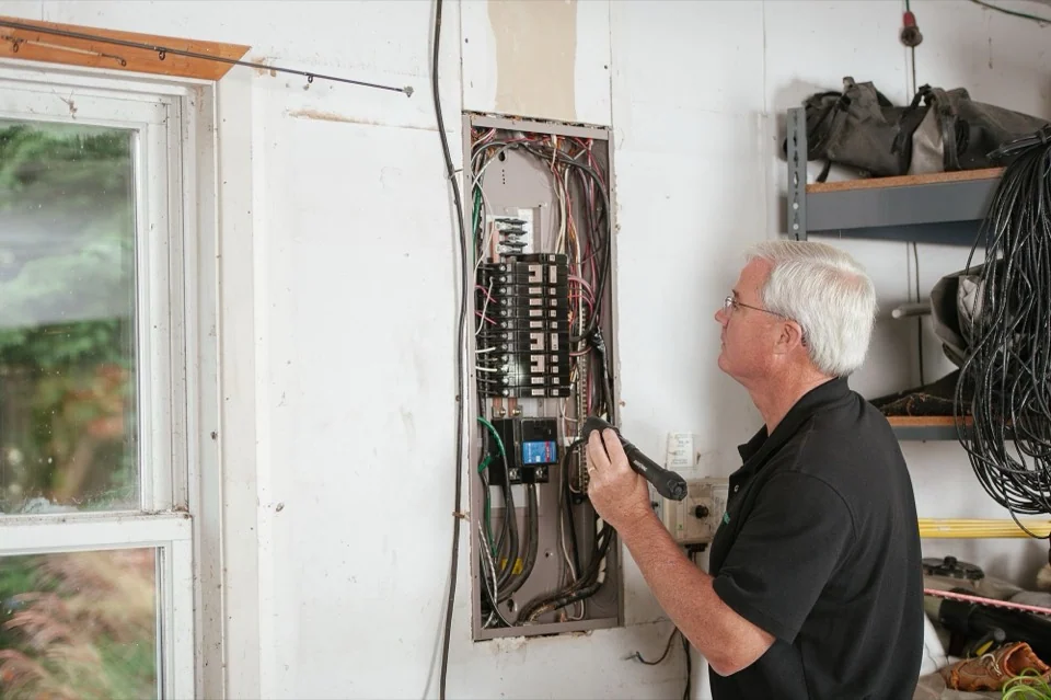
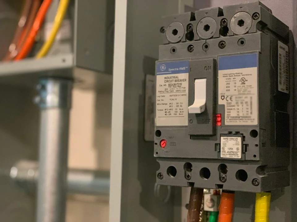
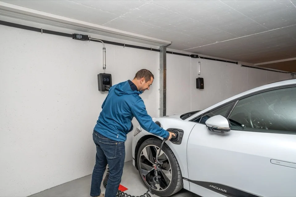
Choose a system to change the scene and go directly to the relevant service page. Photography is representative, never presented as completed Vortex work.

Whole-home assessment
Before adding loads, the service, panel condition, grounding, available capacity and installation constraints are reviewed together.
Service and distribution
Load calculation, equipment ratings, conductors, overcurrent protection, grounding, bonding and utility coordination are treated as one design.
EV charging
Available capacity, charging current, circuit length, equipment listing and the actual parking arrangement determine the installation.
Residential lighting
Fixture location, dimming compatibility, switching intent and lighting-control infrastructure are coordinated before finishes close the work.
Lutron control
Keypads, compatible loads, device locations, scenes and motorized-shade requirements are coordinated as one complete system.
Scope
Open any one of them and you get the whole story — how it works, the code it is built to, and what is verified and documented.
The service and panel distribute utility power to feeders and branch circuits. Overcurrent protection, conductors and connected equipment must be coordinated under the applicable NEC rules rather than by one rule of thumb. An upgrade begins with the load calculation and field verification; the panel, service conductors, meter equipment, grounding and bonding are replaced or retained according to the actual scope, ratings, utility requirements and condition.
The applicable scope is coordinated with NEC Articles 220, 230, 250 and 310, equipment instructions and utility requirements. Circuit identification is addressed under 408.4. A typed directory is our documentation standard; anchorage is evaluated under the applicable building and site requirements.
The proposal identifies the calculation basis, existing service ratings, proposed equipment and outage coordination. The closeout scope includes the updated directory and applicable inspection records.
The proposal defines the anticipated outage, utility coordination, inspection sequence and restoration conditions. Duration depends on the existing installation and authorized scope. The included calculation and circuit-directory records are identified before work begins.
Insurance requirements depend on the carrier and policy. A panel assessment can document the manufacturer, model, ratings, visible condition and identified concerns. The insurer determines acceptance; a replacement should not be promised to guarantee coverage.
Those are two different jobs and they are priced differently. The panel is the enclosure and the busbar; the service is the utility conductors, the meter and the main disconnect. An Article 220 load calculation is what tells you which one is actually short. Sometimes the honest answer is that neither needs replacing and what you need is two new circuits.
A subpanel may be appropriate when the existing service has adequate calculated capacity and a suitable feeder route. It adds circuit spaces, not service capacity. The assessment compares those conditions before recommending a service change.
A Level 2 charger runs on 240 V and is a continuous load — it pulls its full current for hours, not seconds. The code makes you size a continuous load’s circuit at 125% of its rating, which is why a 48 A charger sits on a 60 A breaker with wire to match. The other half of the problem is the panel: the charger has to fit alongside everything else already running.
EV charging is treated as a continuous load. We size the branch circuit and overcurrent protection accordingly, verify available capacity with the applicable load calculation, evaluate voltage drop as a design consideration and obtain the permit when required.
The charger model, configured current, available capacity and cable route are identified before installation. The agreed scope includes setup and a functional charging check.
Most Level 2 installations are half a day when the panel has spare capacity and the run from panel to parking space is reasonable. Longer runs, an outdoor route, or a panel with no space change that. The circuit is permitted and inspected like any other branch circuit, and we set the charger's current limit to match the circuit we actually installed before we leave.
Not always, and the load calculation is what decides it rather than the age of the house. When the calculation comes up short, load management equipment can sometimes let the charger share the capacity you already have instead of paying for a service change. That option gets checked before we quote the expensive path.
Because charging is a continuous load: it draws its full current for hours, not seconds. The code sizes a continuous load's circuit at 125% of its rating, which puts a 48 A charger on a 60 A breaker with conductors and terminations to match. An installer who puts it on a 50 A circuit is not saving you money, they are building something that will nuisance-trip and run warm.
It depends on the unit's listing and where it is going. A plug-in unit needs a receptacle rated for it, and receptacles supplying EV equipment have their own GFCI requirement. Outdoors or in a damp garage the enclosure rating and the mounting height matter too. We match the method to the equipment you bought instead of assuming.
Fixture spacing and offset are selected from the ceiling height, beam distribution, delivered lumens, room surfaces and the task plane. A layout must address both illumination and visual comfort; there is no single wall-offset rule that works for every room or luminaire.
We select housings for contact with insulation where applicable, use trims listed for the actual damp or wet location, maintain clearances required by the luminaire listing and leave every splice accessible in an approved enclosure.
Fixture locations, color temperature, beam selection and control compatibility are coordinated with the room and ceiling conditions. Approved positions and adjustments are recorded.
Often, but access, framing and the wiring route control what is practical. The proposal identifies required openings and who restores the finish.
That depends on the exact fixture, driver and control combination. Compatibility is checked before ordering and the operating range is adjusted during commissioning.
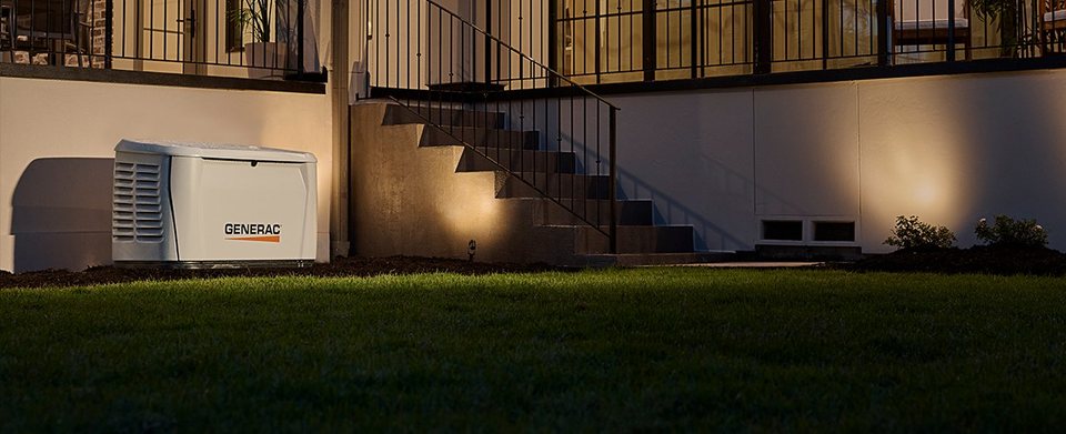
A transfer switch physically disconnects your house from the utility before it connects the generator. That mechanical interlock is the whole point: without it, generator power can push back out onto the utility line and energise it while a crew is working on it. The switch senses the outage, waits for the generator to come up to speed, transfers, and hands the load back automatically when the power returns.
Home standby systems use transfer equipment listed for the purpose. Whether the neutral is switched determines the separately derived system and bonding arrangement, so the generator, transfer switch, service bonding and grounding must be designed as one coordinated system.
The selected-load schedule states what will operate during an outage. Equipment ratings, transfer arrangement, load management, fuel coordination and the commissioning scope are identified in the proposal.
A standby installation is normally two stages: the pad, the transfer equipment and the electrical work, then the fuel connection, startup and load test. Permits usually cover more than the electrical scope, and the transfer equipment is inspected before the unit is commissioned. We hand over the load list the sizing was based on, so a year from now nobody has to guess why the generator is the size it is.
No. Feeding a home through a dryer receptacle can expose people to energized pins and backfeed utility conductors. Do not use that arrangement. A qualified installer should specify an appropriate generator inlet and transfer arrangement for the equipment and installation.
It is a load question and a fuel question at the same time. Covering everything means a larger unit, a larger fuel supply and a larger bill; covering a defined set of circuits means deciding in advance what actually matters to you, which is usually the air conditioning, the refrigerator, some lighting, the well or pool pump and the outlets you charge phones on. We price both so you are choosing, not guessing.
The transfer arrangement controls how the selected loads receive utility or generator power and prevents unintended backfeed when correctly designed and installed. Its ratings, operating sequence and compatibility belong in the proposed standby-power scope.
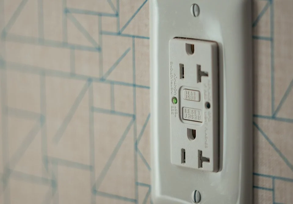
A GFCI compares the current going out on the hot with the current coming back on the neutral. If about five milliamps goes missing, it is leaving through something that is not the wire — often a person — and it opens in under a tenth of a second. An AFCI does something else entirely: it listens to the circuit for the erratic electrical signature of an arc inside a damaged cable, and trips before that arc starts a fire.
NEC 210.8 identifies the specific locations and outlets that require GFCI protection; the applicable list depends on the adopted edition and the installation. NEC 210.12 addresses AFCI protection, and 406.12 addresses tamper-resistant receptacles in dwelling units.
Affected circuits, device types, observed symptoms and test findings are recorded. Corrective work addresses the identified cause and retains the required protective functions.
Adding or correcting protection in a few locations is usually a short visit. The part that takes the time is not the device, it is tracing what is downstream of it, because one protected device often covers several outlets and nobody wrote down which ones. We map and label what we find, so the next person who stands in front of that panel is not starting from zero.
Usually not. A GFCI trips because current is leaving the circuit on a path it should not be taking, and in South Florida the most common cause is moisture — an outdoor box, a bathroom, a pool area, a fixture that fills with water in the rainy season. Long circuit runs and certain motor loads also produce real leakage. A tripping GFCI is normally reporting something rather than malfunctioning, which is why replacing it without finding the cause tends to buy you a few weeks.
They protect against different things. A GFCI watches for current leaking to ground and is there to stop you being electrocuted. An AFCI listens for the electrical signature of arcing and is there to stop a fire starting inside a wall. They are not interchangeable, and the code requires them in different places, which is why some circuits end up with both.
A new code edition does not by itself determine the scope of work on an existing home. Alterations, replacements, unsafe conditions and applicable existing-building rules may trigger specific requirements. We identify the permit scope and adopted rules before recommending corrections.
Older solid-aluminum branch-circuit wiring can develop high-resistance connections where a termination is loose, damaged, oxidized or not identified for the conductor. The correct response begins by identifying the wiring, devices and actual condition rather than assuming every aluminum-wired home needs the same repair.
Any retained conductor must terminate in equipment or a connector identified for the conductor material and installed in accordance with its listing and instructions. Depending on the wiring condition, the repair may use a listed remediation system or circuit replacement; the scope must be accepted for the actual installation and AHJ.
The assessment identifies accessible wiring, observed connection conditions and inspection limits. The proposal separates retained wiring, repairs, replacement circuits and finish restoration responsibilities.
This one varies more than any other job on this list, because the answer depends on what is behind the walls and how much of it can be reached. We start with an assessment rather than a price: what wiring method you actually have, where the accessible connections are, and which of the recognised repair options your house is a candidate for. You get that in writing before anything is opened up.
Homes built roughly between 1965 and the early 1970s are the usual candidates, and the cable jacket is normally marked AL or ALUMINUM where it is visible. Do not open the panel to look. Aluminum used for the service entrance or for a large appliance feeder is a different and normal thing; the concern is aluminum on the small branch circuits feeding your outlets and switches.
Not necessarily. The wiring condition, connection method, device compatibility and access determine whether a recognized connection repair or circuit replacement is appropriate. The assessment documents the observed condition and the limits of the inspection before recommending a scope.
Commonly, yes. Wiring type is one of the items on a Florida four-point inspection, alongside the panel, and it is one of the things that can hold up a renewal or a new policy. Documentation of what was found and what was repaired, with photographs, is usually what the underwriter is asking for.
Dwelling kitchens require at least two 20-ampere small-appliance branch circuits for the receptacle outlets covered by NEC 210.52(B). Fixed appliances and cooking equipment are then evaluated individually for load, listing and manufacturer instructions; some require individual branch circuits. That circuit planning should occur before cabinets and equipment are ordered.
NEC 210.11 and 210.52 establish required small-appliance circuits and receptacle locations. NEC 210.8 applies GFCI protection to the outlets and locations listed in the adopted edition, while luminaires near tubs and showers must meet 410.10.
Appliance data and the cabinet layout are coordinated with circuit capacity, receptacle locations and lighting controls. Electrical rough-in locations are reviewed before concealment.
Before the appliance and cabinet selections are finalized. Equipment data, receptacle locations and lighting should be coordinated while changes are still practical.
No. Available circuit spaces and calculated electrical capacity are separate checks. The existing system is evaluated against the proposed appliances before an upgrade is recommended.

Pool safety depends in part on reducing voltage gradients among the conductive parts identified by NEC 680.26. The equipotential bonding system may include the pool shell, perimeter surface, water, specified metallic components and electrical equipment according to the construction and listed exceptions—not simply every nearby metal object.
NEC 680.26 identifies the conductive parts that must be included in the equipotential bonding system and its permitted methods. Article 680 also coordinates wiring methods and GFCI protection for pool equipment; outdoor covers and underground runs are selected for the actual location and installation.
The scope identifies pool equipment, applicable bonding points, wiring routes and wet-location equipment. Included photographs document accessible concealed work; photographs alone do not establish code compliance.
No. Equipotential bonding reduces voltage differences between the conductive parts covered by the pool requirements. Equipment grounding provides a fault-current path. The installation must address both functions where applicable.
The existing niche, luminaire, transformer, circuit and protective devices must be identified first. The replacement must be suitable for that specific installation and its listing requirements.
Whole-home surge protection at the service equipment. Installation scope and duration depend on the existing equipment and site conditions.
lightning events per square mile placed Florida first in U.S. state lightning density in 2025. That is the local reason. Separately, NEC 230.67 requires surge protection for services supplying dwelling units and addresses replacement service equipment; the adopted code and permitted scope control each project.
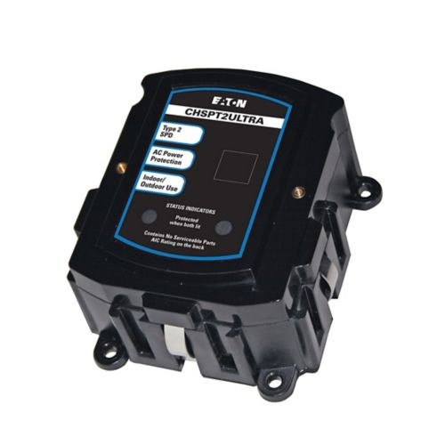
Vaisala Xweather · Annual Lightning Report, 2025A surge protective device limits transient voltage by diverting surge current through low-impedance paths between the connected conductors. Its effectiveness depends on the SPD type and rating, conductor length and routing, bonding, service arrangement and installation instructions. Status indication and replacement criteria are product-specific.
NEC 230.67 requires a listed Type 1 or Type 2 surge protective device for services supplying dwelling units. Placement and installation must follow the adopted code, the device listing, and manufacturer instructions; Article 242 contains additional application requirements.
SPD selection considers the system voltage, listed type, protection modes and manufacturer data. VPR, nominal discharge current, MCOV and SCCR describe different characteristics; no single number guarantees protection for every surge.
A plug-in strip protects whatever is plugged into that one strip. It does nothing for the equipment that is wired in and cannot be unplugged — the air handler and condenser, the range, the water heater, the pool pump, the garage door opener, the low-voltage transformers behind your lighting. Those are usually the most expensive things in the house to replace, and they are the ones a service-level device is there to cover. The two layers are complementary, not alternatives.
A straightforward service-equipment installation is normally one to two hours. Power is off for part of that, so we agree the window with you first. We verify the service arrangement and available fault current, keep the SPD conductors as short and straight as the instructions require — lead length is one of the few things that measurably changes performance — and before we leave we show you the status indicator and write the device model, its ratings and the install date into your closeout record.
The selected model and its system compatibility are documented. Handover identifies the status indicators, manufacturer instructions and replacement criteria.
NEC 230.67 requires a Type 1 or Type 2 surge protective device at the service of a dwelling unit, and it also applies when service equipment is replaced. Florida adopts the NEC through the Florida Building Code, so the requirement reaches your permit through that path. The edition in force, Florida supplements and your AHJ’s interpretation govern the actual job.
Yes, and for a different reason than most people expect. A strip covers only what is plugged into it. Your air conditioning, range, water heater, pool equipment and lighting transformers are hard-wired and cannot be protected that way. A service-level device covers the whole installation; the strips stay useful as a second layer at the outlet.
A straightforward installation at existing service equipment is normally one to two hours, with the power off for part of it. If the panel has no available space, or the grounding and bonding need correcting first, we tell you before the visit, not during it.
Surge protective devices are consumable. They absorb energy and eventually reach end of life, sometimes after one large event and sometimes after years of small ones. That is what the status indicator on the device is for, and it is why we show you where it is before we leave. Replacement criteria are product-specific and stated in the manufacturer instructions.
Compare the listed device type, system voltage, protection modes, VPR, nominal discharge current, MCOV and SCCR, together with the installation instructions and warranty conditions. These values answer different questions; a joule figure alone is not enough to select the device.
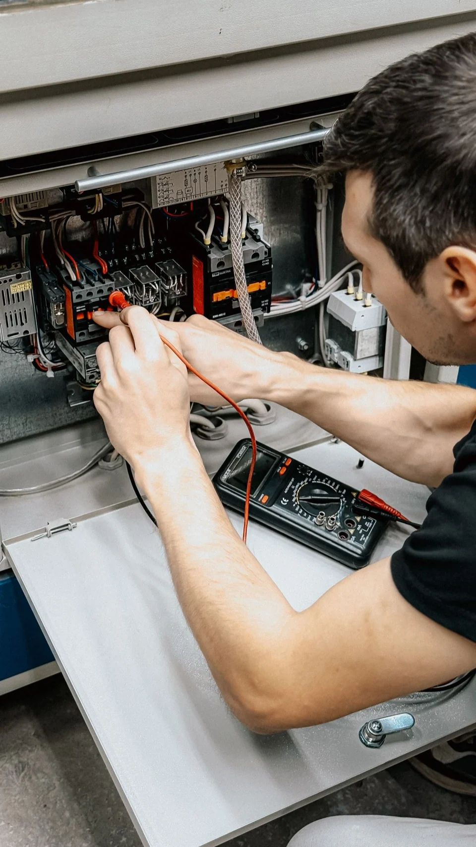
Troubleshooting begins by defining the symptom and making the installation safe. We then use the appropriate combination of visual inspection, measurements, isolation and sectional testing to distinguish among load, conductor, connection, protective-device and supply problems. The method depends on the circuit and access; parts are not replaced merely to see whether the symptom moves.
Repairs use listed components, compliant box fill and accessible splices. Permit requirements depend on the actual scope and the governing AHJ, so that determination is made before work begins.
The diagnostic authorization defines the testing scope and fee. Findings, limitations and repair options are documented separately so the owner can approve the next step.
Not necessarily. Overload, faults, connections, the connected equipment or the protective device may be involved. Testing identifies the cause before a repair is recommended.
Describe the symptoms, affected rooms and when the issue occurs. A photograph of closed equipment may help if it can be taken safely. Do not remove covers or repeatedly reset a tripping device.
Commercial
Offices, retail, restaurants and small warehouses — with shutdowns, equipment and field sequencing coordinated before mobilization.
Scope
Open any one and read how it works, the code behind it, and what is verified and documented.
The affected circuits, outage window, operational constraints and restoration plan are stated in writing. Any night or weekend work and its pricing are agreed in the proposal—not added after the work starts.
Before mobilization, the proposal identifies required insurance documentation, the party responsible for the permit and inspections, and the records included at closeout.
A three-phase system uses phase voltages displaced by 120 electrical degrees. Equipment voltage, phase configuration and load determine the current and conductor requirements. Single-phase loads should be distributed to limit phase imbalance, while neutral loading—including the effect of nonlinear loads and harmonics—must be evaluated rather than assumed to cancel.
Feeders are coordinated under Articles 215, 240 and 310. Working space under 110.26 is not a generic one-metre box: clear depth depends on voltage and condition, while width is the equipment width or 30 inches, whichever is greater. The space must remain clear.
Equipment ratings, calculated demand and available operating measurements are reviewed together. The proposal documents the distribution scope; a spot current reading is not treated as proof of spare capacity.
Distribution work is sequenced around your operation and around the utility, and the utility is usually the long pole. Before a price exists we collect the equipment nameplates, confirm the available fault current at the point of installation, and check that every piece of gear specified can actually be applied there. That is the homework that keeps a switchgear delivery from arriving and not fitting.
Start with the voltage, phase and other requirements on the equipment nameplates. These are checked against the available electrical service before a connection or service change is proposed. Reviewing the equipment schedule before purchasing helps avoid incompatible selections.
Because every piece of equipment has a short-circuit current rating, and it has to equal or exceed the fault current available where it is installed. Gear applied above its rating is not a performance problem, it is a safety problem — it is the difference between a breaker interrupting a fault and a breaker becoming part of it. The code also requires service equipment other than dwellings to be field-marked with that value, so the next person has it.
Further than most people expect, and the reason is rarely us. Utility coordination and switchgear lead times run the schedule, and both have got longer in recent years. Bring us in while the equipment list is still being decided rather than after the lease is signed and the opening date is advertised.

LED retrofit savings depend on the existing fixture input watts, proposed system watts, operating hours, controls and maintained light level. Occupancy controls can reduce unnecessary operating time, and daylight-responsive controls can reduce electric lighting in qualifying daylight zones. We calculate the opportunity from the actual baseline rather than promise a standard percentage.
Retrofit kits must be listed for the application and installed with the required markings and instructions. The Florida Energy Conservation Code adds automatic shutoff, occupancy and daylight-responsive controls in applicable commercial spaces and zones, subject to its stated exceptions.
The fixture schedule identifies wattage, color temperature, controls and compatibility. Any savings estimate records the baseline and operating-hour assumptions; final adjustments are reviewed with the facility team.
Retrofits are scheduled around trading hours, which usually means nights or a phased area-by-area sequence so nothing closes. Before that, we log your real operating hours and measure what is installed, because a payback figure built on a brochure's assumed hours is not a payback figure. Sensor time delays get set with the people who actually work in the space, not from the ladder.
From four things that are yours rather than the manufacturer's: the input watts of what is installed now, the system watts of what is proposed, your actual operating hours, and the light level you have to maintain for the space to still work. Controls change the hours, which is often where more of the saving comes from than the lamp itself. If a proposal gives you a payback without asking for your hours, it made them up.
For a lot of commercial spaces the Florida Energy Conservation Code brings automatic shutoff and occupancy requirements with the work, so it is often not a choice. Even where it is, the controls are usually the part of the project that pays for itself fastest, because an empty room at the correct light level still costs the same as a full one.
The work sequence is agreed before installation. Depending on access and the scope, work may be organized by area or outside business hours. The proposal identifies expected interruptions, access restrictions and fixture lead times.
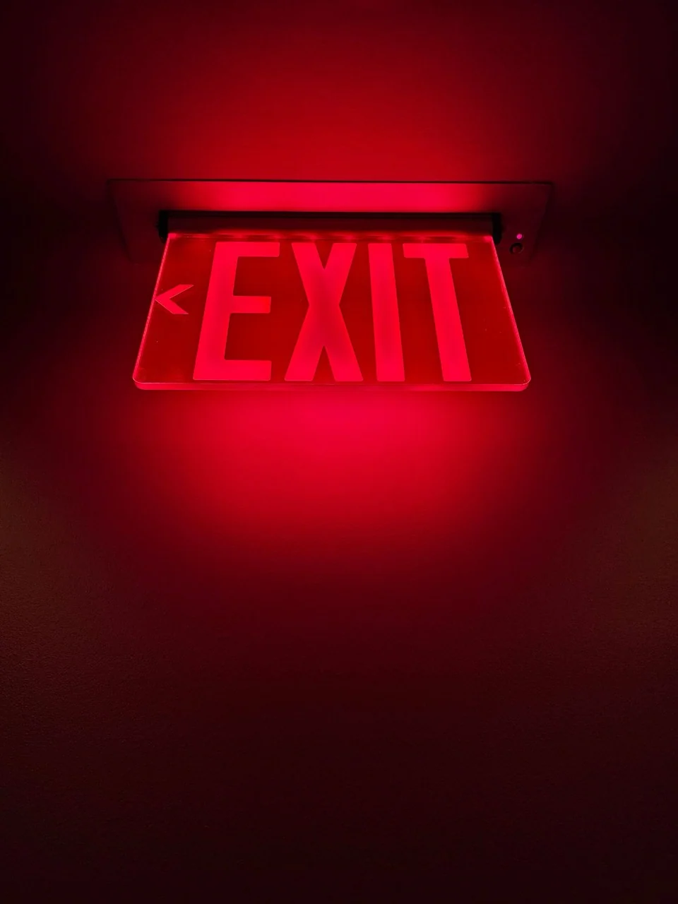
Emergency illumination is coordinated for the actual occupancy and egress arrangement. Where the adopted life-safety and building codes require the common 90-minute duration, the selected source, fixtures and controls must maintain the prescribed illumination for that period—not merely turn on during a brief test.
Emergency-system wiring is coordinated under NEC Article 700, while illumination and testing requirements come from the adopted life-safety and building codes. Where the monthly and annual tests apply, we provide a clear test procedure and record format for the owner.
The scope identifies egress areas, equipment and applicable acceptance criteria. Commissioning records the included functional tests and any required duration or illumination verification.
We walk the actual egress path with the plan, not just the fixture schedule, because the requirement is illumination along the way out rather than a fixture count. Testing is scheduled around your hours. What you get back is a record: fixture locations, battery dates, test results and the failures we corrected, in a format your fire inspector will accept and your insurer will read.
Under NFPA 101, battery-powered emergency lighting gets a functional test of at least 30 seconds every month and a full 90-minute test once a year, with written records kept and available. Florida adopts NFPA 101 through the Florida Fire Prevention Code. In practice most citations we see are not missing fixtures — they are missing records for fixtures that were there the whole time.
Maintenance and testing responsibilities should be identified between the owner and occupant, consistent with applicable requirements. The assessment identifies the equipment and records in scope; unresolved responsibility should be clarified before scheduling the work.
Batteries at end of life that still light the lamp for a few seconds but cannot hold 90 minutes; heads aimed at a wall instead of the path; and the record book. A unit that passes the button test and fails the annual duration test is the single most common finding, which is exactly why the 90-minute test exists.
Electrical rough-in has to land between the framer finishing and the drywall going up. Miss that window and either the schedule slips or someone cuts holes in finished walls. Everything else follows from it: the panel schedule, the circuit count for the equipment the tenant is bringing, the lighting layout the landlord already approved, and the low-voltage pathways nobody drew.
Load calculation for the new occupancy under Article 220, branch circuits and receptacle spacing under 210, and the whole package permitted under the Florida Building Code with the landlord’s own construction rules layered on top.
Rough-in, equipment and inspection milestones are defined with the project team. Field changes are documented with their scope and schedule impact before proceeding.
Yes, when the occupancy, system arrangement and inspection sequence allow it. Temporary conditions, shutdowns and access limits must be defined with the project team.
The current drawing set, equipment schedule, scope limits and desired milestones. Existing-condition verification and unresolved design questions are identified separately.
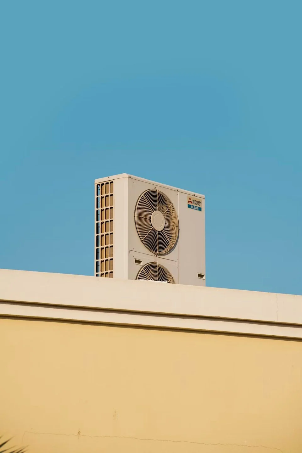
On a normal circuit one device protects against both overload and short circuit. A motor is different: it draws several times its running current for a second every time it starts, so the breaker is sized generously to let that inrush through, and a separate overload device sized close to the nameplate protects the motor itself. Size the breaker like a normal circuit and it trips on every start; size the overload like a breaker and the motor burns.
Motor circuits follow Article 430 and air-conditioning equipment follows Article 440. Conductor, overcurrent protection and disconnect requirements are coordinated from the equipment data and the applicable article—not a rule of thumb. Disconnect location and working space are verified for the specific equipment and any permitted exception.
Nameplate data, approved submittals and installation instructions support the conductor, protection and disconnect selection. The agreed scope identifies connection and startup responsibilities.
The nameplate, approved submittal and installation instructions. Voltage, phase, current and equipment-specific protection requirements determine the connection scope.
Electrical connection and manufacturer startup are different responsibilities. The proposal states what is included and whether another qualified equipment provider is required.
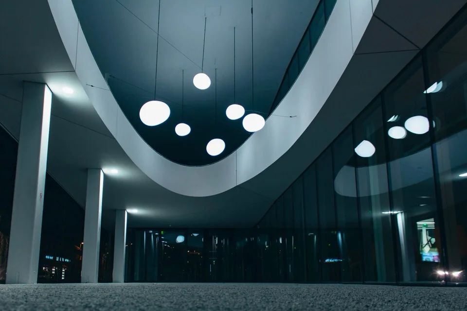
Lighting scenes give staff a consistent setting for each use of a room. The scope defines the controlled loads, button labels and agreed light levels for service, cleaning and closing.
Applicable commercial spaces and daylight zones must meet the control requirements of the Florida Energy Conservation Code, including its exceptions. Dimmers and drivers are selected as a compatible system and installed in accordance with their listings and instructions.
Scene names, schedules and staff controls are agreed with the operator. Commissioning records final settings and provides a practical walkthrough for the people using the space.
A suitable system can provide labeled wall controls for daily operation. Button functions and access permissions are agreed with the operator.
Potentially. Driver type, dimming method, circuit arrangement and condition must be identified. Compatibility is confirmed before the control system is selected.
Almost every correction notice cites the exact code section it is written against. That matters, because the fix for “insufficient working clearance” is completely different from the fix for “unapproved conductor termination”, and guessing which one the inspector meant is how a re-inspection gets failed twice. We read the citation, look at what is actually installed, and price the work against the section rather than against a hunch.
The correction is made to the edition of the code in force on your permit, which is not always the newest one. We confirm which cycle applies before quoting, because the wrong edition is its own failed inspection.
Each correction is tracked against the written notice, observed condition and applicable requirement. The proposal defines corrective work, supporting records and reinspection responsibility.
Yes. Include the notice, permit number, relevant drawings and available photographs. The applicable requirement and observed condition are reviewed together.
No contractor can decide the AHJ outcome. The work and supporting records are prepared against the identified requirements; additional findings or scope changes are documented.
Sign and site lighting live outside the building and outside your daily attention, which is why they are the loads most likely to run twenty-four hours for a year before anyone notices. A photocell handles dusk and dawn on its own; a timeclock handles the hours you actually want. Pole bases, buried feeders and the transition from underground to the fixture are where salt air and water do their work.
NEC 600.6 requires an accessible disconnect for signs and outline lighting, with location methods and exceptions defined by that section. Outdoor branch circuits and underground wiring are then coordinated under Articles 225 and 300 for the actual installation.
The scope records equipment locations, circuit identification and the selected control schedule. Disconnect access and underground routing are verified for the actual installation.
A compatible timeclock or lighting control can be configured for the agreed operating schedule. Photocell behavior and seasonal changes are coordinated with that schedule.
Not automatically. Existing wiring condition, grounding, ratings and the replacement load must be evaluated. Excavation is included only when the defined scope requires it.
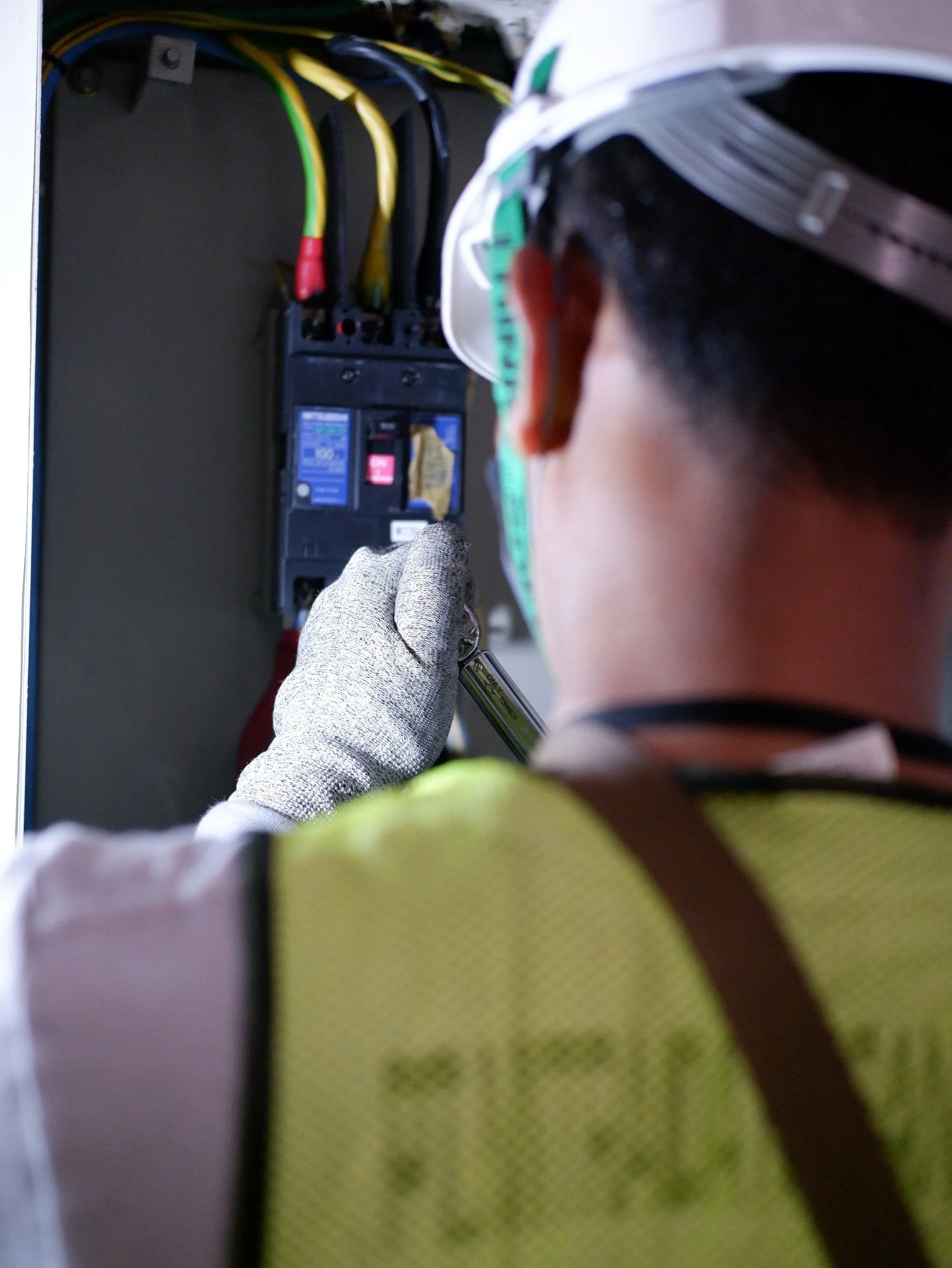
When a restaurant loses a circuit at seven on a Friday, the expensive part is not the repair, it is the twenty minutes spent working out what you have. We keep your panel schedule, your equipment list with nameplate data, and the photos from the original install on file. The call starts with someone who already knows which panel feeds that wall.
The maintenance program is based on the equipment condition, manufacturer instructions and the applicable NFPA 70B tasks. It may include visual inspection, cleaning, thermography and electrical testing; de-energization, access and any termination work are planned for the specific equipment. NEC 110.26 working space must remain clear.
The maintenance report separates observed conditions, test results and limitations. Findings are prioritized by safety and operational impact, with a defined recommendation for each item.
Some inspections can be planned around operations; other tests or repairs require an outage. The maintenance scope identifies access, de-energization and the agreed schedule.
The equipment inspected, observed conditions, tests performed, limitations and prioritized recommendations. It is a record of the agreed assessment, not a blanket certification of the entire building.
Project inquiry
Home or business, one outlet or a complete electrical system. Send the project details and we will confirm the appropriate next step.
Visits by appointment, subject to availability. Contact hours do not imply immediate dispatch or 24-hour emergency service.
Location
Based in Miami-Dade, Florida. Contact Vortex Contractor by email, phone or WhatsApp Business.
Before you call
Tell us the location and the work you have in mind. We will confirm the next step and communicate any applicable visit, assessment or diagnostic fees before scheduling. The proposed work is quoted according to its scope.
Registered Electrical Contractor ER13016872, held by Yarlos Rodriguez Suarez, doing business as Vortex Contractor LLC. Verify the current authorized jurisdictions through DBPR.
Verify licence with DBPRFrom a load calculation and a written scope, not from the size of the panel or a guess at the box count. For service and panel work that means an Article 220 calculation we show you before the price. The proposal lists what is included, what is excluded, who the responsible lead is, and the closeout terms, so you can set it side by side with another quote and see where they differ.
Yes. Estimates, proposals and closeout documentation are available in English or Spanish, and this entire site can be read in either language using the EN / ES switch in the header.
The city, a short description of the work, and a photo of your panel with the cover on if you can take one safely. For anything involving a service or panel change, the age of the home and the appliances you are planning to add matter more than anything else, because they drive the load calculation.
If there is fire, smoke, a burning smell, sparking, or a panel that is hot to the touch, stay away from the equipment and call 911 from a safe location first. Do not open or touch a damaged panel. Once the situation is safe, call us and we will tell you honestly whether it needs attention today or can wait for a scheduled visit.